EMC
Ook op Europees niveau moeten veel producten voldoen aan Europese wettelijke eisen, die zijn vastgelegd in Europese richtlijnen. De belangrijkste van deze richtlijnen zijn: de Machinerichtlijn, de Laagspanningsrichtlijn en de EMC-richtlijn (= elektromagnetische compatibiliteit). Het voldoen aan de eisen maakt de fabrikant zichtbaar door de letters CE (Conformité Européenne) aan te brengen. Als uitwerking van de eisen in de richtlijnen worden Europese normen gemaakt. Wie zich aan de normen houdt, wordt geacht zich ook aan de wettelijke eisen te houden. Werken conform normen is daarom de eenvoudigste manier om aan die wettelijke eisen te voldoen.
Elektromagnetische compatibiliteit (EMC) - Deel 4-11: Beproevingen en meettechnieken - Immuniteitsproeven voor kortstondige spanningsdalingen en -onderbrekingen en spanningsvariaties.
Onderstaand zijn enkele belangrijke aspecten uit de norm IEC-61000-4-11 weergegeven (bron: NENNormshop).
General (4)
Electrical and electronic equipment may be affected by voltage dips, short interruptions or voltage variations of power supply.
Voltage dips and short interruptions are caused by faults in the network, primarily short circuits (see also IEC 61000-2-8), in installations or by sudden large changes of load. In certain cases, two or more consecutive dips or interruptions may occur. Voltage variations are caused by continuously varying loads connected to the network.
These phenomena are random in nature and can be minimally characterized for the purpose of laboratory simulation in terms of the deviation from the rated voltage and duration.
Consequently, different types of tests are specified in this standard to simulate the effects of abrupt voltage change. These tests are to be used only for particular and justified cases under the responsibility of product specification or product committees.
It is the responsibility of the product committees to establish which phenomena among the ones considered in this standard are relevant and to decide on the applicability of the test.
Test levels (5)
The voltages in this standard use the rated voltage for the equipment (UT) as a basis for voltage test level specification.
Where the equipment has a rated voltage range the following shall apply:
- If the voltage range does not exceed 20% of the lower voltage specified for the rated voltage range, a single voltage within that range may be specified as a basis for test level specification (UT);
- In all other cases, the test procedure shall be applied for both the lowest and highest voltages declared in the voltage range;
- Guidance for the selection of test levels and durations is given in IEC 61000-2-8.
Voltage dips and short interruptions (5.1)
The change between UT and the changed voltage is abrupt. The step can start and stop at any phase angle on the mains voltage. The following test voltage levels ( in % UT ) are used: 0%., 40%, 70% and 80%, corresponding to dips with residual voltages of 0%, 40%, 70% and 80%.
For voltage dips, the preferred test levels and durations are given in table 1.
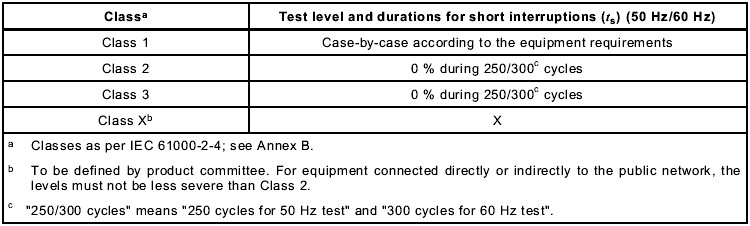
For short interruptions, the preferred test levels and durations are given in table 2
The preferred test levels and durations given in table 1 and 2 take into account the information given in IEC61000-2-8.
The preferred test levels in Table 1 are reasonably severe, and are representative of many real world dips, but are not intended to guarantee immunity to all voltage dips. More severe dips, for example 0% for 1 s and balanced three-phase dips, may be considered by product committees.
The levels and durations shall be given in the product specification. A test level of 0% corresponds to a total supply voltage interruption. In practice, a test voltage level from 0% to 20% of the rated voltage may be considered as a total interruption. Shorter durations in the table, in particular the half-cycle, should be tested to be sure that the equipment under test (EUT) operates within the performance limits specified for it.
When setting performance criteria for disturbances of 0,5 period duration for products with a mains transformer, product committees should pay particular attention to effects which may result from inrush currents. For such products, these may reach 10 to 40 times the rated current because of magnetic flux saturation of the transformer core after the voltage dip.
Table 1: Preferred test level and durations for voltage dips
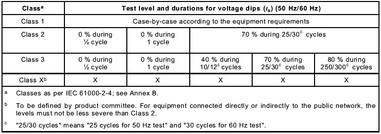
Table 2: Preferred test level and durations for short interruptions
Voltage variations (optional, 5.2)
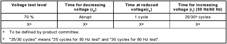
This test considers a defined transition between rated voltage UT and the changed voltage. Note: the voltage change takes place over a short period and may occur due to change of load.
The preferred duration of the voltage changes and the time for which the reduced voltages are to be maintained are given in Table 3. The rate of change should be constant; however, the voltage may be stepped. The steps should be positioned at zero crossings, and should be no larger than 10% of UT . Steps under 1% of UT are considered as constant rates of change of voltage.
Table 3: Timing of short-term supply voltage variations
Annex B (informative) Electromagnetic environment classes
B1 Electromagnetic environment classes
The following classes of electromagnetic environment classes have been summarised from IEC-61000-2-4.
- Class 1
This class applies to protected supplies and compatibility levels lower than public network levels. It relates to the use of equipment very sensitive to disturbances in the power supply, for instance the instrumentation of technological laboratories, some automation and protection equipment, some computers, etc.
Note: Class 1 environments normally contain equipment which requires protection by such apparatus as uninterruptible power supplies (UPS), filters, or surge suppressers.
- Class 2
This class applies to points of common coupling (PCC’s for consumer systems) and in-plant points of common coupling (IPC’s) in the industrial environment in general. The compatibility levels in this class are identical to those of public networks; therefore components designed for application in public networks may be used in this class of industrial environment.
- Class 3
This class applies only to IPC’s in industrial environments. It has higher compatibility levels than those of class 2 for some disturbance phenomena. For instance, this class should be considered when any of the following conditions are met:
- a major part of the load is fed through converters;
- welding machines are present; - large motors are frequently started;
- loads vary rapidly.
Note 1: The supply to highly disturbing loads, such as arc-furnaces and large converters which are generally supplied from segregated bus-bar, frequently has disturbance levels in excess of class 3 (harsh environment). In such special situations, the compatibility levels should be agreed upon.
Note 2: The class applicable for new plants and extensions of existing plants should relate to the type of equipment and process under consideration.